

How do you select a helical rotor flow meter based on medium viscosity, flow rate, and pressure?
Release time: 2026-09-22
Helical rotor flow meters have become essential liquid metering devices in sectors such as petrochemicals, lubricating oil transfer, fuel metering, resin filling, adhesive blending, and hydraulic systems. This is due to their positive displacement measurement principle, high repeatability, and suitability for medium-to-high viscosity liquids. When selecting a model, one cannot rely solely on pipe diameter or maximum flow rate; it is also necessary to consider the medium’s viscosity at operating temperature, the flow rate range (from minimum to maximum), system operating pressure, allowable pressure loss, as well as the presence of impurities and temperature conditions. This article focuses on these three key operating parameters to explain how to select the most suitable helical rotor flow meter configuration. These meters are typically used for high-precision positive displacement measurement applications involving high-viscosity, abrasive, or filler-laden liquids.
Table of Contents
Why are helical rotor flow meters suitable for viscous liquids?
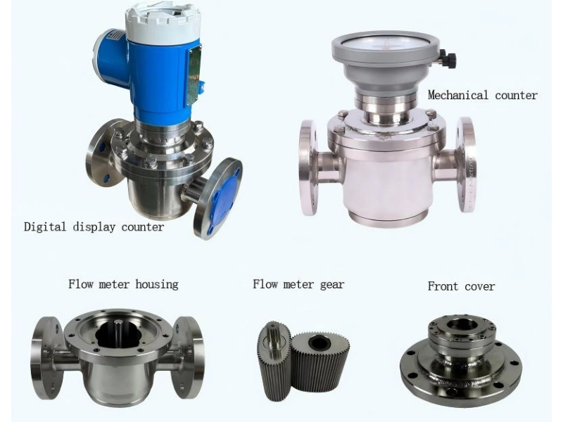
Helical rotor flow meters are a type of positive displacement flow meter. Internally, they consist of one or more sets of precision-machined helical rotors. As liquid enters the metering chamber, it is continuously partitioned into discrete volumes—formed between the rotors and the housing—and transported to the outlet. Each full rotation corresponds to a relatively fixed displacement; the meter calculates instantaneous and cumulative flow rates by detecting rotor speed or pulse count.
Compared to instruments that infer flow rate based on velocity or differential pressure, positive displacement designs generally handle low flow velocities and high-viscosity liquids more effectively. A moderate increase in viscosity can reduce internal leakage through clearances and potentially improve volumetric efficiency; however, higher viscosity does not allow for unlimited operation. Increased viscosity raises rotor resistance and meter pressure loss; therefore, selection must be adjusted (derated) based on the “flow rate–viscosity–pressure drop” curves provided by the manufacturer. For instance, some helical gear flow meters can measure viscosities ranging from approximately 3 to 300,000 cP, but the maximum allowable flow rate decreases as viscosity rises.
How does medium viscosity influence model selection?
Viscosity is one of the most critical medium parameters when selecting a helical rotor flow meter; however, it is essential to consider the viscosity at the actual operating temperature rather than relying on data sheet values based on ambient temperature. The viscosity of media such as oils, resins, adhesives, and polymers varies significantly with temperature: viscosity generally decreases as temperature rises, while it may increase—or even lead to solidification, crystallization, or severely impaired flow—as temperature falls.
When selecting a meter, viscosity data for minimum, normal, and maximum operating temperatures should be provided to the supplier; common units include mPa·s, cP, or cSt. For liquids with a density close to 1 g/cm³, 1 mPa·s is approximately equal to 1 cP; however, kinematic viscosity (cSt) and dynamic viscosity (cP) are not directly equivalent, as their relationship depends on density. Therefore, if process data specifies cSt, the medium’s density or specific gravity should also be provided.
At low viscosities, internal slippage (leakage) between the rotor and the metering chamber may increase—particularly under high differential pressure or after equipment wear—potentially affecting measurement accuracy. For low-viscosity applications, it is essential to verify the meter’s minimum viscosity limit, minimum measurable flow rate, and actual accuracy curve. For high-viscosity applications, the focus should shift to pressure drop, start-up capability, residual discharge pressure, and thermal insulation measures. Research indicates that leakage in helical rotor flow meters increases with differential pressure and decreases with higher liquid viscosity; thus, viscosity and differential pressure must be evaluated in conjunction.
How should the flow range be matched to the meter size?
When selecting a flow meter, first determine the process’s minimum, normal, and maximum flow rates, as well as whether the flow is continuous and stable, intermittent, or pulsating. Relying solely on the criterion that “maximum flow does not exceed the meter’s range” is insufficient; long-term operation near either the minimum or maximum limits of the range can compromise stability and service life.
It is recommended that the normal operating flow rate fall within the middle of the meter’s recommended operating range, rather than consistently operating near the upper limit. For systems involving pump start-stop cycles, variable frequency drive (VFD) regulation, or batch filling, instantaneous peak flow rates must also be factored into calculations. If the maximum flow rate exceeds the meter’s rated upper limit, rotor speeds may become excessive, increasing bearing loads and accelerating wear; conversely, if the minimum flow rate falls below the meter’s stable measurement limit, pulse output may become unstable, and repeatability may deteriorate. It is crucial to note that the flow meter size should not simply be matched mechanically to the pipeline diameter. For high-viscosity liquids, a larger meter size might reduce flow velocity and pressure loss, but it could also cause actual low flow rates to fall into an unfavorable measurement range; conversely, while a smaller size improves resolution at low flow rates, it significantly increases pressure drop. Therefore, the correct approach is to determine the size based on the flow range and pressure drop curve corresponding to the actual viscosity, rather than selecting the model solely based on the existing pipe diameter.
Why must pressure and pressure loss be verified simultaneously?
System operating pressure, maximum pressure capacity, and allowable pressure loss are three distinct concepts that should not be conflated.
Operating pressure refers to the pressure within the pipeline or equipment during normal operation; it is used to verify the pressure ratings of the flow meter housing, flanges, seals, and connections.
Maximum pressure accounts for peak pressures that may occur during events such as pump startup, valve switching, water hammer, or blockages; the flow meter’s rated pressure should include an adequate safety margin.
Allowable pressure loss refers to the pressure drop generated as the liquid passes through the flow meter. Even if the meter has sufficient pressure resistance, excessive pressure loss can lead to increased pump load, insufficient downstream supply, reduced flow rates, or difficulties in transporting high-viscosity media.
Helical rotor flow meters rely on the pressure difference between the inlet and outlet to drive rotor movement, but a higher pressure difference is not necessarily better. High pressure differentials can increase internal leakage, seal loads, and mechanical wear; furthermore, as viscosity increases, the pressure drop at a given flow rate also rises. Selection guidelines for mechanical flow meters suggest that for high-viscosity media, the maximum flow rate should be derated based on the meter’s pressure drop curve, and the pressure drop should be kept within the limits acceptable to the system.
How are viscosity, flow rate, and pressure calculated together?
Actual selection can follow the sequence of “medium first, then flow rate, and finally pressure loss”: first, determine the actual viscosity based on temperature; next, establish the minimum, normal, and maximum flow rates; and finally, consult the pressure drop curve for the target model at the corresponding viscosity. If the manufacturer provides a pressure loss calculation formula, use the actual specific gravity, kinematic viscosity, and flow rate to verify the figures, rather than relying on rated parameters based on water or low-viscosity liquids. The following table serves as a basic checklist when submitting selection specifications to flow meter suppliers:
| Parameter Category | Information to Confirm | Main Impact on Selection | Recommended Approach |
|---|---|---|---|
| Fluid Name and Composition | Lubricating oil, fuel, resin, adhesive, chemical liquid, or other media; whether the fluid contains solvents, corrosive components, solid particles, or fibers | Determines flow meter material, rotor design, sealing materials, and filtration requirements | Provide the fluid name, MSDS, or main chemical composition. If the fluid contains particles or fibers, confirm the filtration solution in advance. |
| Dynamic Viscosity | Viscosity at the minimum, normal, and maximum operating temperatures, usually expressed in mPa·s or cP | Affects internal leakage, rotor resistance, measurement accuracy, and pressure drop | Do not provide viscosity only at room temperature. Use viscosity data under actual operating temperatures. |
| Kinematic Viscosity and Density | Kinematic viscosity in cSt, plus fluid density or specific gravity (SG) | Used for viscosity conversion and pressure-drop verification | If only cSt is available, provide the fluid density at the same temperature. Avoid treating cP and cSt as directly interchangeable values. |
| Flow Range | Minimum, normal, maximum, and instantaneous peak flow rates | Determines meter size, measuring range, rotor speed, and low-flow stability | Keep the normal operating flow within the recommended working range whenever possible. Peak flow must not exceed the meter’s maximum allowable flow rate. |
| Operating Pressure and Peak Pressure | Normal operating pressure, pump outlet pressure, valve-switching pressure, and possible pressure surges | Determines pressure rating, connection standard, and sealing configuration | The meter pressure rating should exceed the maximum possible system pressure and include an appropriate engineering safety margin. |
| Allowable Pressure Drop | Maximum acceptable differential pressure across the flow meter | Determines whether a larger meter size, lower flow rate, or pump adjustment is required | Calculate pressure drop at the highest viscosity and maximum flow condition. Confirm that sufficient downstream pressure remains for stable process operation. |
| Temperature Range | Minimum, normal, and maximum process temperatures; whether heat tracing, insulation, or cleaning is required | Affects viscosity, seal material selection, body material, electronic components, and installation method | For fluids that may solidify at low temperatures or degrade at high temperatures, include heat tracing, insulation, and drainability requirements in the design. |
| Accuracy and Output Requirements | Whether the application requires instantaneous flow, totalized flow, batch control, or custody transfer; pulse output, 4–20 mA, RS485, or other signals | Determines sensor configuration, transmitter type, local display, and control-system interface | Define the required accuracy class, repeatability, minimum resolution, K-factor, display requirements, and communication protocol before selection. |
| Fluid Cleanliness and Solids Content | Whether the fluid contains metal particles, crystals, fibers, sediment, or other abrasive contaminants | Affects rotor wear, blockage risk, filtration requirements, and long-term measurement stability | Install a suitable upstream strainer or filter when necessary, and establish regular inspection and cleaning procedures. |
| Installation and Maintenance Conditions | Available installation space, pipe direction, bypass requirements, accessibility, ambient temperature, vibration, and maintenance frequency | Affects installation configuration, serviceability, long-term reliability, and downtime risk | Confirm the installation orientation and straight-pipe requirements with the supplier. For critical applications, consider a bypass line to allow maintenance without interrupting the process. |
Data for some helical rotor flow meters indicates that pressure drop typically increases with flow rate and is influenced by specific gravity and kinematic viscosity; therefore, calculations must be based on the actual medium and flow rate, rather than relying solely on rated flow data from the catalog.
What other on-site conditions should be considered?
In addition to viscosity, flow rate, and pressure, factors such as medium lubricity, cleanliness, corrosiveness, gas bubble content, installation space, and maintenance conditions should be evaluated. Helical rotor flow meters contain precision-fitted internal components and are generally best suited for clean, non-abrasive liquids with adequate lubricity. If the medium contains hard particles, metal shavings, crystals, fibers, or incompletely mixed solids, it may cause rotor jamming, wear, or measurement errors; consequently, a filter with an appropriate filtration rating should be installed at the inlet, accompanied by differential pressure monitoring and regular cleaning.
For high-viscosity liquids or those prone to solidifying at low temperatures, measures such as thermal insulation, heat tracing, and low-point drainage should be considered to prevent the medium from solidifying inside the meter during shutdowns. In systems with significant pumping pulsation, the impact of fluctuations on readings can be mitigated through flow stabilization measures, optimal installation positioning, or signal damping. If the medium is corrosive, the material compatibility of the housing, rotors, and seals must be verified; decisions should not be based solely on viscosity and flow rate.
Selecting a helical rotor flow meter is essentially about finding a reliable balance between viscosity, flow rate, and pressure: for low-viscosity applications, the focus should be on verifying internal leakage and low-flow accuracy; for high-viscosity media, attention must be paid to pressure loss, residual pump pressure, start-up performance, and heat tracing/insulation requirements; for projects with significant flow fluctuations, it is essential to ensure that the normal flow rate falls within the recommended operating range and to avoid exceeding the meter’s maximum range during peak flows. Hefei Yutuo’s experience in industrial flow measurement projects demonstrates that accurate selection must be based on the complete operating conditions, rather than just pipe diameter or catalog parameters. To ensure the most reliable selection of model, materials, seals, and signal configurations, it is recommended to provide details regarding fluid composition, temperature-viscosity data, minimum/normal/maximum flow rates, operating and peak pressures, allowable pressure drop, particle characteristics, and output requirements during the inquiry stage. Hefei Yutuo also offers various flow measurement solutions—such as dual rotor flow meter—and can assist in evaluating the appropriate measurement approach based on your specific requirements for accuracy, pressure, temperature, and communication.